Construction Drawings: Types, Formats, and How to Read Them
The first documents a general contractor sees when negotiating any job are construction drawings. Regardless of the project type, the drawings are the “groundwork” of construction project management.
Construction drawings are actionable instructions showing valuable information from dimensions and materials to structural systems and installation details. They are important as general contractors rely on the document to understand the full scope of work and potential risks, and coordinate work with architects and engineers.
Besides, it’s the document that the contractor needs during the takeoff phase of the project. In this guide, we’ll break down what construction drawings include, the different types the contractors may encounter, and how to read and manage them effectively.
Table of Contents
- What Are Construction Drawings?
- Why Construction Drawings Matter
- Types of Construction Drawings
- Reading Construction Drawings
- How Contractors Work with Sets of Drawings
What Are Construction Drawings?

Construction drawings are visual documents presenting how a building should be constructed. They are somehow the language of a designer and engineer to the contractor team that will execute the project.
The drawings represent precise instructions, show dimensions, materials, layouts, and other details. There are other terms that can be confused with drawings. They are used interchangeably in informal communication, but there is a difference:
- Construction drawings are the complete set of visual documents used during a project.
- Blueprint, as a formal term, is not used any longer as it was a reproduction that could not be edited, unlike any digital copy used now. The term is used informally now to describe printed or digital drawing sheets.
- Specifications are written documents that accompany drawings, describing materials, installation methods, quality requirements, etc.
Who Creates Construction Drawings?
It depends on the type of drawing we are talking about. Usually, a team of designers and engineers develops construction drawings.
- Architects typically lead the creation of construction drawings. They are responsible for the overall design, layout, and functionality of the building.
- Structural engineers design the framework of the building, including foundations, beams, columns, and load-bearing elements.
- Civil engineers may handle site-related drawings during infrastructure projects outside the building (grading, drainage, and utilities).
- MEP Engineers develop drawings with a focus on HVAC systems, ventilation, lighting, water supply, and other building systems.
Why Construction Drawings Matter
Unlike early-stage sketches showing a concept, the drawings in construction are legally binding documents. Besides, they include exact dimensions that are important for the entire construction process.
Here are several reasons why it is important to read the drawings efficiently and store them properly:
Accurate Estimating and Takeoffs
They serve as a source of truth for the budget starting from the preconstruction phase. Estimators rely on drawings to measure materials, labor, and quantity takeoff. Without a clear document, the takeoff may be inaccurate and lead to cost overruns and lost profit margins.
Recommended reading:
Improved Coordination Across Teams
These documents are a shared reference point for many stakeholders, including engineers, architects, contractors, and subcontractors. Coordinated drawings help prevent disputes and misunderstandings, which is important for minimizing rework.
Better Planning
Drawings are important for the construction project management by helping teams sequence tasks, allocate resources, and develop realistic timelines. When teams understand the full scope visually, they can plan workflows more effectively.
Documentation Management
These documents serve as a legal reference throughout the project, ensuring that work meets regulatory and contractual requirements. In addition, the contractors and project owners need them when requesting permits and conducting inspections.
Most importantly, the drawings are not a single document, but a set of different drawing types, and each serves a specific objective. Let’s consider the main types.

Types of Construction Drawings
To better understand the types, let’s divide them into four main categories according to their function and use during the project.
Architectural Drawings Related to Layout and Design
This is the most common type of drawing, defining the layout, the actual look, and placement of the building.
Site Plan: This plan provides an overhead view of the entire area, showing how the building is positioned within the property. It includes property lines, landscaping, access roads, parking areas, and nearby structures. The plan can have a 2D or 3D format for a more realistic view of the future building.
Thus, this drawing helps general contractors understand site conditions, logistics, and how the project integrates with the neighboring properties.
Floor Plan: This horizontal plan shows each level of the building. It is a layout including room distribution, wall locations, doors, windows, and circulation paths. The floor plan can also display the places for furniture. They are used for estimating, takeoffs, and day-to-day construction activities.

Elevations show the height of the building and the finish materials (siding, brick, windows). It’s a vertical view of the building’s exterior from different angles. In particular, architectural style, proportions, and finishing materials visualize how the building will look once it is ready.

Sections are vertical cut-through views of the building showing what’s happening inside the walls, floors, and roofs.
Structural and Engineering Drawings
The architectural drawings show what the building will look like, while these documents focus on the technical details of the job. Thus, they reveal how the building will stand and function.

Structural drawings are the “skeleton” of the building, defining the load-bearing elements, including beams, columns, sabs, and reinforcement. For example, one of the subtypes is the framing plan with information about the sizes and positions of the beams. The example above shows bracing details. It explains how walls are reinforced to resist lateral forces such as wind loads, ensuring overall building stability.
Mechanical, electrical, and plumbing drawings cover the building’s essential systems that make it functional. They provide information about:
- HVAC systems, ductwork, ventilation, and climate control
- Power distribution, lighting, wiring, panels, and circuits
- Water supply, drainage, piping, and fixtures
These drawings are used by specialized subcontractors to install and coordinate systems within the building. Proper coordination of MEP drawings is crucial to avoid clashes (e.g., ducts interfering with structural elements) and ensure efficient system performance.
Fire Drawings focus on systems designed to detect and prevent the spread of fire. They include layouts for sprinkler systems, fire alarms, smoke detectors, fire extinguishers, and emergency exit routes. These drawings must comply with strict local codes and regulations and are essential for securing permits and passing inspections.
Detail Drawings
These blueprints show how a specific part of the building or infrastructure should be constructed.
Shop drawings are highly detailed documents. Unlike other types, they are created by subcontractors or manufacturers, not the design team. They explain how a specific building component will be manufactured, assembled, and installed.
They can be used for:
- Steel structures (beams, connections, bolts)
- Joinery and cabinetry (kitchen cabinets, built-in furniture)
- Curtain walls and façade systems
- Precast concrete elements
For example, for a commercial building façade, a curtain wall supplier will create shop drawings showing exact glass panel sizes and aluminum framing details.
Reflected Ceiling Plan (RCP) is a unique view of the ceiling with lighting, vents, and sprinklers as if you were looking at a mirror on the floor. They are typically prepared by architects in coordination with MEP engineers to ensure the systems fit together without conflicts.
They include:
- Lighting layout (recessed lights, pendants, chandeliers, emergency lighting)
- HVAC components (air diffusers, return vents, exhaust grilles)
- Ceiling finishes (gypsum board, acoustic panels, suspended ceilings)
- Coordination with structure (beams, slabs, and height restrictions)
Construction Record Drawings
They explain what changes were made after the construction project was completed.
As-Built Drawings are the final versions that reflect the actual conditions of the completed building. Unlike architectural drawings showing what is planned, they show what has been built, including all modifications.
They are typically prepared by contractors or project engineers after construction is complete, based on real site changes, field adjustments, and approved variations.
Thus, they are important as they serve as a project record for handover and closeout, and help in the case of future renovations or expansions.
Reading Construction Drawings
A complete set of construction drawings includes standard elements found on almost every construction sheet. Each component serves a specific purpose and provides critical details for different teams.
Here is a breakdown of key elements found on a typical set of construction drawings:
Title Block
This block is an ID card of the drawing. It is usually located on the right side or the bottom of the document and contains:
- project name
- date
- Number
- scale (e.g. 1:200)
- author (designer, architect)
- contact information (email, phone number, etc.)

Legend and Symbols
The document includes a dedicated legend area to explain the lines and visuals used by the designers.

They represent specific elements such as “stud walls” (double parallel lines) and “blockwork walls” (hatched double lines). There are also structural indicators. For example, specific symbols mark new installations, such as a dashed-and-dotted line for a “new steel PFC neam” or a square with a circle for a “75×75 SHS Post”.
To keep the sheets clean and readable, some abbreviations are used, for example, GB for glass bricks.
Beyond materials, graphic symbols and abbreviations are used to show specific fixtures and structural members. Overall, icons are used for everything from electrical outlets and plumbing fixtures to the direction of a door swing.
Notes
The documents are heavily annotated with various types of notes that provide specific instructions. They can be found on almost every page of a drawing set, usually grouped in the margins or near specific details. For instance, the notes can state that the setbacks have to be confirmed by a surveyor prior to building approval.
Another type is compliance notes that ensure the project meets local and national safety standards. These notes often refer to the regulatory bodies, specifying that elements like smoke alarms or ventilation systems.

Technical notes also usually present key data, such as earthworks specifications with a detailed breakdown of fill material type, angles of embankments, and other details.
As the notes can change from page to page, a project manager must read the specific notes attached to each individual sheet.

How Contractors Work with Sets of Drawings
It’s clear that general contractors deal with the drawings at all stages of the projects. Let’s see how it works in practice:
Estimating
General contractors and estimators use floor plans and sections to calculate exactly how much concrete, timber, or drywall is needed. By reading the technical notes and schedules, they assign costs to materials and labor to create a competitive bid.
At this stage, the contractors spot risks, for instance, areas where the architectural and structural plans don’t align.
Planning and Coordination
Once the contractor starts execution, drawings are the foundation for planning. Architectural, structural, and MEP drawings are reviewed together to ensure all systems fit within the same space without conflicts.
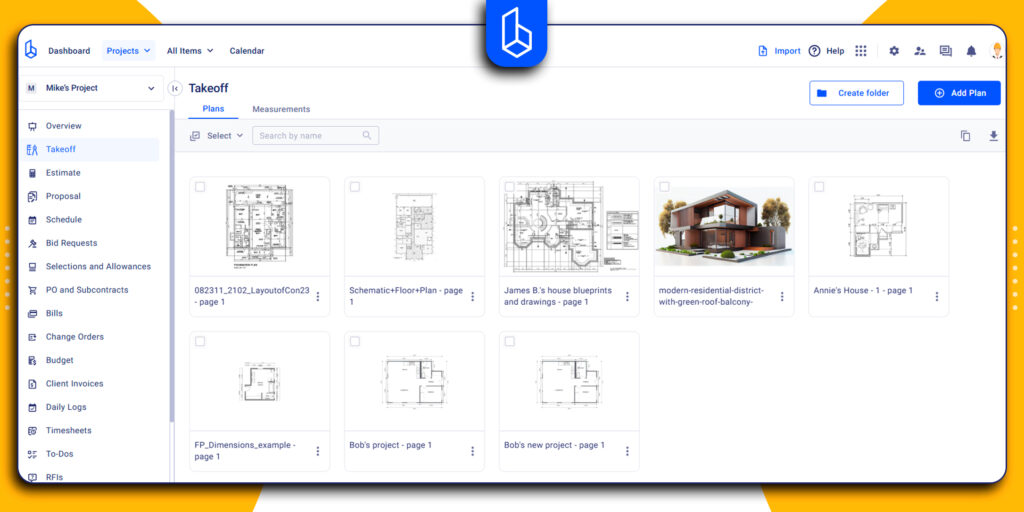
Thus, they help break projects into phases and assign responsibilities to subcontractors, sending their particular sets (only the MEP and structural pages to the plumber). In addition, it’s essential to have a clear document management software to have all files stored in one hub and be shared with the subcontractors’ dedicated portals.

Revisions
Not all drawings are perfect, and the execution of the construction project requires a constant dialogue between the contractor and the design team.
Moreover, if contractors or subs find a missing dimension or an unclear note, they issue a Request for Information (RFI) to clarify the drawing before work proceeds.

Recommended reading:
The detailed shop drawings provided by the subs, on the contrary, are sent by contractors for the approval of the architect and engineering teams. This submittal process ensures that they match the original construction drawings, and further work is approved.
Handover and Project Closeout
At the final stage, the documents are the primary tools for a smooth transition from contractor to owner. Contractors compile all updated documentation into a final package, including as-built drawings.
In addition, they are reviewed alongside inspection reports, change orders, and compliance certificates. This ensures that every modification meets local building codes. Accurate as-built documents help project owners locate hidden systems (like plumbing or electrical lines inside walls) for future maintenance, repairs, or renovations.

How to Read Construction Drawings?
Start from the title block, scale, and legend to understand the sheet. Pay attention to notes, symbols, and revisions to ensure accurate execution and avoid missing critical details during construction.
What is a Match Line in Construction Drawing?
A match line is a reference line used to divide large drawings into smaller ones. It shows where one sheet continues onto another. The purpose is to ensure continuity of plans, like floor layouts or site plans, when they cannot fit on a single page.
What Are Shop Drawings in Construction?
Shop drawings are detailed drawings created by subcontractors or manufacturers. They show specific components of the building, for instance, cabinetry or curtain walls, that will be made and installed.